
DIY Rocket Altimeter: Step-by-Step Guide
Creating a DIY rocket altimeter is a great way to track your rocket's altitude, save money, and learn new skills. Using affordable components like an Arduino Nano and a BMP280 barometric sensor, you can measure altitude, log flight data, and even control parachute deployment. Here's the process in a nutshell:
- What It Does: Measures altitude using pressure changes, logs data, and can trigger recovery systems.
- Why Build One: Costs as little as £17–£38, teaches electronics and programming, and allows customisation.
- Key Components: Microcontroller (£4–£8), barometric sensor (£3–£10), SD card module (£2–£4), LiPo battery (£5–£8), and more.
- Tools Needed: Soldering iron, multimeter, and basic hand tools.
- Steps: Assemble components, solder connections, program with Arduino IDE, test, and calibrate.
- Testing: Verify data logging, sensor accuracy, and recovery system functionality before launch.
This guide covers everything from assembly to programming and troubleshooting, ensuring your altimeter works reliably during flight.
Building the Eggtimer Apogee | DIY Rocket Altimeter & Parachute Deployment System
Components and Tools You'll Need
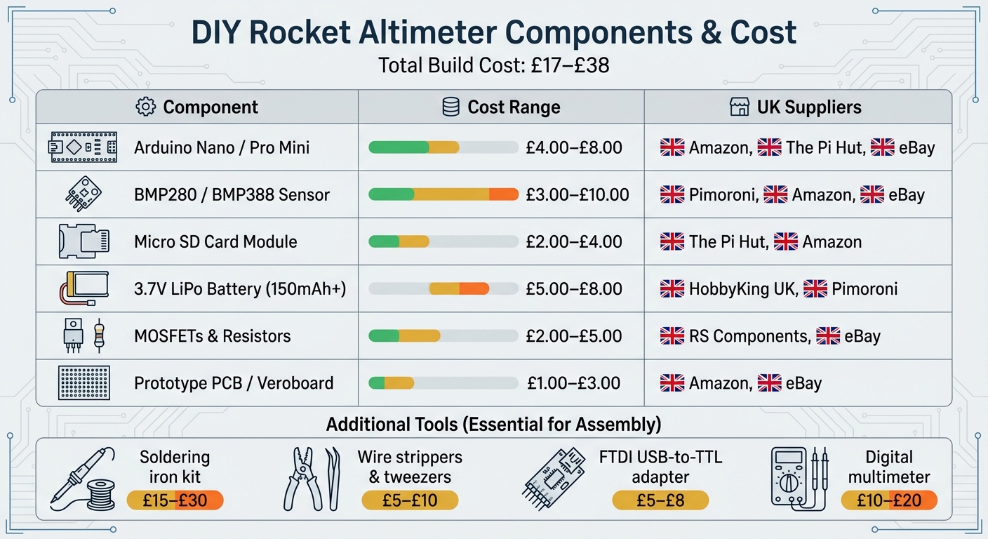
DIY Rocket Altimeter Components Cost Breakdown and UK Suppliers
Creating a functional rocket altimeter involves assembling a range of electronic components and tools. The total cost typically falls between £17.00 and £38.00, and most items can be sourced from UK-based suppliers with quick delivery times.
Key Components for the Altimeter
At the heart of your altimeter is the microcontroller, which processes sensor data and logs flight information. Popular choices include the Arduino Nano, featuring an integrated USB connection, or the Arduino Pro Mini, which is more compact (priced between £4.00 and £8.00) but requires an FTDI adapter for programming. For an even smaller option, consider the TinyDuino.
The barometric sensor measures altitude by detecting atmospheric pressure. The BMP280 is a reliable choice, usually costing between £3.00 and £10.00. For those seeking higher precision, the BMP388 or MS5611 are excellent alternatives.
For data storage, you can opt for a Micro SD card module (around £2.00–£4.00) for extensive logging or a compact I2C serial EEPROM such as the 24LC512.
A 3.7V Lithium Polymer battery (150mAh to 400mAh, priced at approximately £5.00–£8.00) powers the system. These lightweight, high-energy batteries are available from suppliers like HobbyKing UK and Pimoroni.
For dual-deployment systems, you'll need N-Channel MOSFETs (e.g., FDS6898AZ) and resistors (£2.00–£5.00) to handle the high current required for pyrotechnic igniters. To indicate system status, consider adding a piezo buzzer or LEDs. A prototype PCB or Veroboard (costing £1.00–£3.00) is useful for mounting components securely.
| Component | Estimated Cost | UK Suppliers |
|---|---|---|
| Arduino Nano / Pro Mini | £4.00–£8.00 | Amazon, The Pi Hut, eBay |
| BMP280 / BMP388 Sensor | £3.00–£10.00 | Pimoroni, Amazon, eBay |
| Micro SD Card Module | £2.00–£4.00 | The Pi Hut, Amazon |
| 3.7V LiPo Battery (150mAh+) | £5.00–£8.00 | HobbyKing UK, Pimoroni |
| MOSFETs & Resistors | £2.00–£5.00 | RS Components, eBay |
| Prototype PCB / Veroboard | £1.00–£3.00 | Amazon, eBay |
Once you've gathered these components, you'll need the right tools and safety practices to assemble everything.
Tools and Safety Precautions
A soldering iron kit is essential, with prices ranging from £15 to £30. Additional tools like wire strippers and tweezers (around £5–£10) are handy for preparing wires and handling small parts. If you're using the Arduino Pro Mini, an FTDI USB-to-TTL adapter (typically £5–£8) is required for programming. A digital multimeter (priced at £10–£20) is invaluable for troubleshooting connections and checking battery voltage.
When soldering, ensure you're working in a well-ventilated area. A PCB holder can help secure components during the process. If you're charging small LiPo batteries with a TP4056 charger, replace the standard RPROG resistor with a 10k 0805 surface mount resistor to limit the charging current to a safe 100mA.
A hot glue gun can be used to secure and insulate connections, but take care not to block the vent hole on your barometric sensor. Your rocket's electronics bay should also have static ports - small holes that allow internal pressure to equalise with the external atmosphere. Finally, always store LiPo batteries in a fire-proof bag and avoid short-circuiting the terminals.
Assembly Instructions
Put together the altimeter carefully to ensure it can withstand the intense forces experienced during flight.
Preparing the Components
Begin by dry-fitting all components onto your board to check their fit, spacing, and alignment with the mounting holes. Use a multimeter to test each part - confirm the barometric sensor is working and the microcontroller powers up as it should.
Start soldering by attaching pin headers to the sensor breakout boards and the microcontroller. If your microcontroller needs extra programming components, temporarily secure the headers until the code is uploaded. For connections that might need frequent adjustments - like those for pyrotechnic charges or external switches - use 2-pin terminal blocks. These provide a balance between secure connections and easy removability. A well-organised layout is crucial for dependable altitude tracking during flight.
Soldering and Connecting Components
When soldering, aim for strong and reliable connections. Avoid standard push-fit jumper wires in model rocketry; they can disconnect under high accelerations, which can reach around 5G. Instead, use sturdy hookup wires and solder all connections firmly. To reduce interference, twist related wires together - for example, those for switches, pyrotechnics, or batteries.
Follow a clear pinout diagram when wiring components like sensors and SD card modules. For instance, if you're using a Seeeduino Xiao with a BMP280 sensor, connect the sensor's SDA to D4 and SCL to D5 for I²C communication. For the SD module, connect its MISO, MOSI, SCK, and CS pins to D9, D10, D8, and D3 respectively. After wiring, protect exposed solder joints with hot glue, but ensure sensor vents remain unobstructed. If you want to monitor battery health, add a 2K–2K voltage divider between the battery's positive terminal and ground, connecting the centre tap to an analogue pin (e.g., A6).
Before powering up, use a multimeter to verify the polarity of your JST connectors and battery. This step is essential to prevent accidental damage.
Mounting the Altimeter in the Rocket
Once all electrical connections are secure, move the assembly into the rocket's dedicated flight chamber. To get accurate altitude readings, the altimeter must be placed in a sealed chamber (also called an AV bay) that’s isolated by bulkheads. This setup prevents pressure disturbances from the nose or vacuum effects at the rear. The chamber should include vent holes, or static ports, to allow the barometric sensor to measure external air pressure accurately. As Richard Nakka from Experimental Rocketry explains:
The altimeter must be installed in a 'sealed' chamber with vents, or static ports, open to the outside.
Mount the electronics on a sturdy sled made of wood, plastic, or PCB material, and secure it inside the rocket’s body tube or payload section. Ensure the chamber has at least four static ports evenly spaced around its circumference. These should be positioned at least four body diameters behind the junction where the nosecone meets the fuselage to ensure smooth airflow.
For example, in July 2018, a builder known as Orion14ed successfully installed a DIY Arduino-based altimeter inside a 4-inch Patriot rocket. Using a long wooden sled, the setup endured approximately 5G of acceleration during an H100 motor burn. The system remained operational thanks to the secure mounting of components, although the builder later recommended replacing loose wires with soldered connections for added durability.
Finally, use sealed bulkheads at both ends of the altimeter chamber to prevent internal pressure spikes. Protect the altimeter from the hot gases and debris produced by recovery ejection charges. Keep pyrotechnic igniters disconnected during assembly and setup, and use DIP switches to ensure the firing circuit remains open until launch.
sbb-itb-f093e97
Programming and Configuration
With the hardware in place, the next step is tackling firmware and configuration. This ensures your altimeter is ready to work seamlessly with your rocket and its flight profile.
Installing and Testing Firmware
To upload code to most DIY altimeters, the Arduino IDE is your go-to tool. For this, make sure you're using version 2.3.7. Start by opening the .ino sketch in the Arduino IDE and connecting your microcontroller via USB. If you're working with a board like the Arduino Pro Mini, which lacks a built-in USB port, you'll need an FTDI USB-to-TTL adapter.
Before uploading the firmware, tweak the key parameters in the code. For example, set the deployment altitude for the main parachute to about 200 metres. This helps reduce wind drift while ensuring the rocket descends safely. Once the parameters are adjusted, compile the sketch and upload it to your hardware. After uploading, open the Serial Monitor (shortcut: F8) to confirm that the sensors are functioning correctly and providing live altitude readings. Once this is verified, you can move on to calibrating the altimeter.
Calibrating the Altimeter
Accurate altitude readings hinge on proper calibration. Most altimeters set their zero reference by averaging barometric pressure readings while the rocket is stationary on the launch pad. After powering on, allow about a minute for the sensors to stabilise.
To arm the altimeter, press the designated button or issue a command while the rocket stays on the pad. This step sets the current location as the 0m reference altitude, based on the barometric pressure at that moment. During calibration, the device typically averages 16 pressure samples to establish a reliable baseline.
Keep in mind that barometric sensors, such as the MS5607, are highly sensitive to direct light, which can distort readings significantly. To avoid this, shield the sensor with opaque materials or use adhesive-backed open-cell foam. This foam blocks light while still allowing airflow. Additionally, ensure your rocket’s avionics bay includes static ports for accurate pressure equalisation. A common guideline is one 6mm diameter hole per 1,650 cubic centimetres of chamber volume.
Once calibration is complete, you can tailor the settings to suit your rocket’s specific performance needs.
Adjusting Settings for Different Rockets
Customising the configuration to match your rocket’s design is crucial. For dual-deployment systems, the main parachute deployment altitude is the most critical setting. Typically, deployment altitudes range between 100m and 300m.
If you're working with multi-stage or air-start rockets, advanced altimeters offer additional programming options. For example, you can configure pyro channels to ignite the next stage when certain velocity thresholds are reached (e.g., 25 m/s to 1,000 m/s) or to detect the end of a booster's thrust phase. Some systems also allow for deployment delays - usually between 1 and 5 seconds after detecting apogee. This delay helps prevent "zippering" by giving the rocket time to slow down and stabilise before deploying the drogue parachute.
For altimeters with configuration software or graphical interfaces, use these tools to adjust settings like deployment heights and metric units. This approach is far more convenient than hard-coding values into the firmware, especially if you plan to use the altimeter across different rockets. Before heading to the launch site, double-check your settings using the Serial Monitor. Also, ensure that the altimeter saves peak altitude data to non-volatile memory. This way, the data remains accessible even if the battery disconnects after landing.
Testing and Data Analysis
Before taking to the skies, it's essential to run thorough ground tests. Start by connecting the device via USB, opening the Arduino IDE Serial Monitor, and checking for proper sensor initialisation and real-time altitude data feedback. Pay close attention to LED blink patterns and beep codes - these provide critical status updates. For example, 'Dit dit' signals readiness, while 'Dit dah dah dit' indicates pad mode.
Manually move the altimeter to ensure the sensors are responding as expected. Follow this with a drop test from a known height to confirm the sample rate of 20–25Hz. To check the continuity of the igniter circuit, listen for beeps that confirm proper connections. For those aiming for high precision, a vacuum chamber can simulate pressure changes at different altitudes, although this step is optional for most hobbyists. These initial tests form the backbone of the more detailed pre-launch checks that follow.
Pre-Launch Testing
On launch day, insert the SD card before powering on the device. Many loggers won’t initialise the card if inserted after power-up. Once powered, leave the altimeter stationary for at least five seconds to allow the barometric and gyroscope sensors to calibrate. Be sure to check the battery voltage beforehand - a low battery or one without a supporting capacitor can cause the altimeter to reboot during a deployment charge. For your first flight, consider running the altimeter in logger-only mode (without deployment charges) to ensure data is being recorded properly before trusting it with recovery tasks.
Retrieving and Reading Altitude Data
After a successful test and flight, it’s time to retrieve the logged data. Power off the device and remove the micro SD card to access it on your computer. Most DIY systems save data in .csv or .txt format, which can be easily opened in Microsoft Excel or Google Sheets. Use the "Text to Columns" feature with a comma delimiter to arrange the raw data into readable columns. If your altimeter logs pressure in Pascals, you’ll need to convert it into altitude using standard atmospheric formulas. For accelerometer readings, divide the raw values by 2,048 to convert them into G-force. Plotting altitude against time will help you clearly identify key phases like launch, apogee, and descent. Some altimeters even provide peak altitude data through a series of beeps after landing, with short beeps representing "0" and long beeps representing "1" in scientific notation.
Troubleshooting Common Problems
If you encounter issues during testing, here are some common problems and their solutions:
- Altimeter reboots mid-flight: Likely caused by a current spike from the ejection charge. Adding an electrolytic capacitor can stabilise the power supply.
- No data on the SD card: This often happens if the card was inserted after the device was powered on. Always insert the card before turning on the device.
- Inaccurate altitude data: Poorly placed static ports are a common culprit. Ensure there’s at least one 6mm hole per 1,650 cubic centimetres of altimeter bay volume, and that the ports are deburred and flush with the fuselage.
- Device not recognised by the PC: This typically indicates missing drivers (like FTDI) or an incorrect COM port selection. Install the necessary drivers and double-check the port settings.
Certain tones can also help diagnose issues: a warble tone signals full onboard storage, while a brap or dissonant tone indicates a continuity problem in the ejection charge circuits.
| Common Problem | Likely Cause | Recommended Solution |
|---|---|---|
| Altimeter reboots mid-flight | Current spike from ejection charge | Add electrolytic capacitor |
| No data on SD card | Card inserted after power-on | Insert SD card before power-on |
| Inaccurate altitude data | Poor static port placement | Reposition ports; seal bulkheads |
| Device not found by PC | Missing drivers or wrong COM port | Install FTDI drivers; verify port |
Conclusion
Summary of the Build Process
Creating a DIY rocket altimeter involves four main steps: selecting components, assembling the hardware, programming the firmware, and testing the system. You’ll start by picking a microcontroller and a barometric sensor, then solder these components onto a PCB to ensure they withstand the rigours of flight. Once the firmware is uploaded to handle data logging and recovery systems, thorough testing becomes essential. This includes calibrating the device, ensuring static ports are correctly positioned, and securing the installation for reliable performance during launch.
To avoid common issues like mid-flight resets or inaccurate data, take extra care with continuity checks, secure connections using hot glue, and conduct drop tests to validate your setup.
Next Steps in Model Rocketry
With your altimeter built and tested, you’re ready to take on new challenges in model rocketry. After mastering basic altitude tracking, you might consider adding dual deployment systems. These systems release a drogue parachute at the rocket's highest point (apogee) and deploy the main parachute at a lower altitude - typically around 215 metres (700 feet) - to ensure a safe and controlled landing. For an even more advanced setup, you could integrate GPS modules for real-time tracking or a 10-axis IMU to capture data on acceleration and rotational speed.
If you’re looking for structured guidance, Rocketry for Schools (https://rocketryforschools.co.uk) offers build kits and team resources to support your next steps. Their electronics kits and class packs are a great way to apply your altimeter skills in educational settings. Whether you’re working solo or as part of a team, these resources can help you progress to more complex projects like air-starting motors or even active flight control systems.
The best part of DIY rocketry is how accessible it is - building a basic altimeter costs just £15 to £20, making aerospace engineering concepts available to virtually anyone. As you expand your skills, consider joining online communities where seasoned builders share tips, troubleshoot common issues, and collaborate on new designs. It’s a fantastic way to learn, connect, and push the boundaries of what you can achieve.
FAQs
How can I get accurate altitude readings with my DIY rocket altimeter?
To get reliable altitude readings from your DIY rocket altimeter, it's crucial to house the device in a secure, sealed payload compartment. This enclosure shields the altimeter from external influences like airflow, sudden pressure shifts, and heat, all of which could disrupt its accuracy.
Choose a high-precision pressure sensor like the BMP388 or MS5611, and make sure it's properly calibrated and connected to your microcontroller. Calibration plays a vital role in ensuring accurate data, so spend time fine-tuning the sensor before launch. Also, inspect all wiring and connections thoroughly to minimise the risk of errors during flight.
What challenges might I encounter when building a DIY rocket altimeter?
Building your own rocket altimeter can be an exciting and fulfilling project, but it does come with its fair share of hurdles. One common issue is incorrect wiring, which can throw your circuits off and prevent them from working as they should. Another challenge is calibrating the sensors - any miscalibration can result in altitude readings that are way off the mark.
You might also encounter power supply instability. Voltage fluctuations can mess with how your components perform, so maintaining a steady power source is key. On top of that, data logging errors can crop up if your storage or software isn't set up properly to capture flight data. To avoid these pitfalls, it's worth investing time in thoroughly testing each step of the process. This extra effort can go a long way in ensuring your altimeter works as planned.
Can this altimeter design be used in different rocket types?
This altimeter design is incredibly flexible, making it a great fit for different types of rockets. It’s built as a multi-purpose electronic system that not only measures altitude but can also handle recovery system deployment. With a few tweaks to its design or components, it can be customised to suit various rocket configurations, making it a practical choice for diverse projects and setups.